Building a £20,000 Epic machine part 3

The fun continues... links are below for parts 1 and 2 Preparing and fitting the cable chains... Silicone will prevent vibrations and noise between the joint Making the cable hole nice and smooth Some plastic trunking for inside the gantry beam This paint seems to never go hard! So I will make some gaskets for all the mating sufaces... Seems like a good time to try a new laser cutter! I like this one because it has wifi, so i can tuck it away Also faster with more powerful diode This one was ridiculously easy to assemble It is literally 6 bolts 2 tensioners and some cable ties. It uses some kind of torque feedback instead of limit switches More futuristic looking than OLM2 PRo Unfortunately, I couldnt get it to wifi with lightburn... At least I can watch my favorite 80's TV programmes Apparently there will be an update, we'll see...
These gaskets will stop the painted parts sticking to things These are 20:1 planetary gear reducers Should give good speed with very high torque and accel/decel And these are 750w Mitsubishi servo motors Nothing ever just fits does it?! Making a flat spot for the grub screw to bite onto The other 3 motors are loosely fitted for now for running cables Fitting the inductive limit switches... This one needs a mounting hole... Making brackets for the switch to detect... Making a bracket for the Y axis limit switch...
Random piece of metal from scrap pile for detected bracket Then decide they are too wide :/ Running some cables... Labelling the cables since they all look the same The cabinet isnt deep enough so I need to angle the servo drives Making angled servo drive brackets... 180g orbital gives a nice brushed finish on old allumbinumb Outlet vent needs a hole as well... Doing all the cutting before the lek-tricks go in Hole for inlet cable gland Brushed apperture for the machine cables to go through Little din rail mounting brackets for mounting the PC... Interface card from yurtaev.com for Mitsubishi servo drives
Slightly re-configuring the cabinet... And all the servo drives are suddenly wired up... Some ribbon cable to link the I/O's on the inerface card... Making sure I didnt do anything stupid Providing a path for electrons to flow into the cabinet... Mounting the PC usb/switch panel to the cabinet door... Any ~200kg flying metal gantry deserves an oh $h!7 button...
Mounting the PC monitor... More random scraps and some riv-nuts.... Thats not windows! Now I have to learn all these weird numbers and letters!... After much confusion I got the Z axis to home Fitting the gear rack for the X axis...
Adjusting for minimal backlash... Adjusting the linear scale using trial and error More confusion and hair loss later and the X axis can home At this point im waiting for parts for the Y axis gear rack... So im assembling the cooling fan/filter for the cabinet The fans blow into the cabinet and pressurise it to keep dust out Some Aluminium for mounting the Y axis gear racks... Putting an aluminium cutting blade into the table saw Cut a piece of wood to the same width as the aluminium...
Test cut, then flip and cut again, observe deviation in cuts Adjust fence and repeat until cut is central Now I can cut aluminium exactly in half Locking gear racks into each other to ensure correct spacing Then mark, drill and tap mounting holes... This cheapo counter-sink bit wont touch the racks... Carbide burrs make good counter-sinks for hard materials Chamfer cutter in router to arris the aluminium edges Using a spring load tap guide to the thread the holes Varifying direction of rotation of other side before engaging gear Calibrating the Y axis scale... Aiming for 2200mm, recalibrate and try again until correct Squaring the gantry....
First I alligned the straight edge along the table.... Then marks its location... Measure out an arc at a convenient known perpendicular point... Then use ancient greek maths to find where is 90 degrees Then allign the straight edge to 90 degrees... And allign the gantry to the straight edge! simples Then crash into the straight edge and start all over again... And finally I can home all the axis's It is kinda freaky how a big lump of metal can stop so quickly Second test of running some g-code... this time with camera on
Fitting a tool length probe... The bracket is temporary until I get the spindle in place The air line will blast any dust from on top of the probe Testing with mock spindle... It automatically measures cutter length after tool changes Adding weight to simulate spindle... This amount of weight is insignificant... But when power is cut, the Z axis sags under the weight...
To prevent crashes I will fit a counterbalance... 25mm bore 300mm stroke air cylinder will act as a spring The bottom wil be plumbed into a reservoir... The top just needs a filter A random old helium cylinder for a reservoir... Removing the residual pressure valve... Now it will operate normally at low pressure Adding inlet, outlet and guage to the broken regulator...
This pipe goes to the counterbalance cylinder... The reservoir is charged to 50psi, giving ~15kgf at the cylinder A minimum of one leak is mandatory on the first attempt 3 miles of ptfe later... The volume of the reservoir ensures a constant spring rate If id have done this earlier id still have a helium regulator Fitting the spindle bracket...
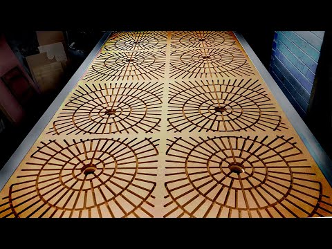
I fitted the spindle cooling lines while waiting for a delivery... Then it arrived... Cutters and collets... More cutters... Spoil board surfacing cutter...
Air solenoid valves.. And an extremely well packaged spindle from Lusintun It is a 3.5kw water cooled auto tool change spindle BT30 tool holder Seems very well put together considering how cheap it was The air pressure went too low :/ After turning compressor on The cooling lines will go a bit close to the pulley Thermoforming and fitting the cooling lines... Random plastic chemical bottle Car windscreen washer bottle seal The radiator will be cooled by the cabinet fan Plumbing compressed air to the tool release... drilled one hole on an erroneous pencil line :) Little coolant flow indicator Filling with antifreeze and de-ionised water It just gurgled the water in the pump so I re-configured it...
Now the pump feeds the bottom of the radiator... And returns into the tank This way it automatically removes air from the system Plumbing air to the tool length probe And a coolant mister for cutting alluuumbinuumb Ill install the coolant bottle here later This idiot just got the tool release pipes backwards :) VFD for the spindle... More confusing numbers and letters Fitting the spindle cable... The spindle earth is connected via the connector body Fold earth wire over the shielding and wrap in copper tape Then the connector clamps onto the earth and shielding Connect shielding to earth wire at cabinet end Doing the boring bit... It spins! Calibrating the speed using lincurve, whatever that is Preloading a few cutters... And remember what they are on some paper I lubricated the gear racks with some dry moly paste It is less sticky than grease so dust shouldn't stick to it I plumbed in a game controller to use as a pendant Touching off with a probe point (was an old reamer) It then measures the probe point and remembers that Then measures the cutter to calculate the offset Yaaay! finally cutting something....
Ill remember to set a ramp angle next time :/ Little tabs hold the pieces while still being cut Making an automatic blast gate... Making the slider smoother and tiny bit thinner... And wax all the sliding surfaces 50mm stroke 40mm bore air cylinder Little needle valve mufflers control the speed Microswitch connects to my existing dust collector system Why isn't there a dust shoe on this bloody machine? Over enthusiastic feed speed...
The shaking actuated the tool probe which stopped the run Try again... Making a better tool length probe bracket... It can move away when machining full sheets Full sheets like this... Making side panels and extra bracing...
All this extra bracing really stiffened up the base a lot Making a tool holder rack... Making a tool holder changing lock thingy... The air pressure is too low to change the tool again... Releasing air to get the compressor to kick in Waiting... l ordered some parts to fix this Making end caps for the gantry beam...
Roughing up the surface of the plywood bed And gluing on a sheet of MDF... Using traditional Yorkshire clamping system... Next day... Cutting air channels for vacuum hold down system... Pipes and flanges to connect the vaccuum motors Waiting for parts again...
The probe air blast is too powereful and noisey.. Adding a needle valve to calm it down a bit Inadequate clamping :/ Also messed up the feed speed, super fast! These are flanges for mounting the vacuum clamp motors Lasering some eva foam gaskets for same motors... I bought three types of motor to try out Milling an aluummiinnuuum control box for the vacuums... I perforated the corners of the 3mm ally for bending Cutting out the base...
A 2kw SCR regulator for each motor Wiring looms for the motors Sheet of basic standard mdf Each zone will have its own motor Air is sucked through the MDF spoilboard to hold materials The single stage 1600w motor was noisey and lacks cooling The two stage 1200w motors are quieter and have cooling 2 stage equals better suction This 1400w 3 stage motor didn't impress, it was twice the price... And the blades scrape against the housing at higher speeds I ordered more of the 2 stage 1200w motors Meanwhile this booster pump arrived to fix the air pressure Random old Co2 bottle for a reservoir Removing residual pressure valve... It doubles the air pressure using science Now the spindle tool release will always work More motors and more flanges... Large facing cutter to skim and level the top of the MDF Using the 8 vacuum motors on minumum speed And skimming one side off the MDF spoilboard This removes the shiny dense face to allow more air to pass Spoilboard is then flipped and glued in place... Hardboard to seal the face to pull the MDF down Sealing the edges to reduce air leaks And a coat of white paint to match rest of machine And top of spoilboard is finally skimmed flat Marking out vacuum zones with sharpy Making a vertical fixture plate for end of machine...
I swapped my liver for this slab of 48mm thick Birch plywood Slot cutter for Festool track clamps Chamfer cutter to bevel the edges More calibrating.. This plate also doubles as bracing for this end of the frame 12mm pins/dogs For clamping work vertically to machine into the edges A good 4 months and 1 inch of beard later.... Im calling this machine and video finished! Thanks for joining me on this epic journey!
2022-10-12 04:08


