А вот и кроссовер для 2х полоски на 6 5 Seas 1 3 Monacor
Hello. Hello audio elders, whitened by audio middles, who did not abandon me in this sorrowful hour. No matter how much the rope twists, you still have to work. Well, we mean doing something with your hands - sawing, planing, and so on. This very moment has come . We figured out the band sections in the previous video for this two-way system here. Let me remind you that it is on Monacor DT-300 and SEAS h1215. Now we need to develop a crossover, which is what I will do now. And I will show you all this in detail. I’ll even show you a couple of options for this crossover. In fact, there can be countless solutions . Well, relatively speaking, a lot, let’s put it this way. All this can be implemented in different ways. I will show you my version, the one that I liked based on, first of all, calculations, that is, an elementary theoretical basis and secondly, on the subjective perception of it all by ear. I’ll say right away that
we assume, but the Lord disposes. That is, what I wanted to divide according to the classics at 2.8 kHz, in general, did not work out. It turned out much higher. Which contradicts, for example, the theory about the distance between the speakers, which I promoted in previous videos, and repeated this several times. However, I stipulated there that in view of the fact that the speaker is not a point source of sound, and yet its dimensions are expanded compared to the point, then the interference that occurs at frequencies above the calculated one also .... In general, let's say interference is not as terrible as the devil... Therefore... In short, now I will show you all this.
So, having created equal conditions necessary for measuring the frequency response to create a crossover, I received the following graphs of the frequency response of these two speakers. This, it’s easy to see, is Monacor DT-300. The frequency response was taken in this field without a filter, of course. Here is a graph of the Seas H1215 speaker, from which, if we add up these graphs, we can see that the high-frequency speaker has greater sensitivity than the low-frequency one. That is, you will have to introduce an L-pad, something like 6 dB minimum, and you will need to take into account the reflection losses of the Baffle Step, which you see here. The losses are huge...
Losses compared to the mid-frequency range losses on the Baffle Step begin with the frequency, which is determined by the empirical formula 11600 divided by the minimum size of the partition in centimeters. That is, for me it is 25 cm. Let's try to do this... Divide 11600 by 25 cm and get the frequency in Hertz. 464 Hz. But you can check yourself. Now I have bookmarked... Such a Baffle Step compensator calculator. The circuit must consist of inductance, shunted by a certain resistor in order to weaken its quality factor, on which the losses introduced by this circuit will depend. In my case I would like to lose 3 dB somewhere.
Looking at this graph, it seems to me that no more should be done, because the filter itself will fall somewhere here at 2.5 to 3 kHz and there will be only so much left to compensate. Although all this is lost money, please understand correctly. To use this formula, you need the DC resistance of this speaker, find it here... I put it aside somewhere... here it is, I have 5.8 Ohms, let's write it down... Baffle width in inches. Well, 25 cm is 10 inches. And the loss in decibels. I would like to lose three
decibels on all this... And we get 456 Hz. Well, and the data of the coil, which is needed with a 0.8 millihenry resistor. We look here on the calculator - it was 464 Hz, here it is 456 Hz. And according to the graph actually taken, we see 456 Hz... here you go, this is where we should start compensating for this entire section, with this chain. Well, let's do that...
In general, we will have to do this, we will have to make these losses, because otherwise the sound will of course be defective. So we're building a crossover. Well, let's call it a "two strip"... passive filter. The width of the Baffle in mm is 250, the height, well, 500... Although I don’t remember. There was something like 480 and you see the distance between the centers of bass and high-frequency radiation, well, in our case, two speaker strips are 15 cm, that is, 150 mm, and what frequency will the program now offer us to divide the strips?? 2300 Hz you think the Linkwitz-Riley filter she offers us. So, the low-pass filter, we need to enter parameters for it... where is it here... Yes, that’s right, the Seas H1215 bass speaker and its resistance, I enter the impedance curve. It determines the DC resistance. Well, in most cases here. Let's move on to the next one
tab. Our high-frequency speaker is a Monacor DT-300, we need to enter its data into this Shaitan-arba, let it count. The DC resistance is this and we will get a filter like this at the output... This is the filter, if we turn on the analysis, it will show us the following curvature. Well, once again - This is without compensation for the Baffle Step, which starts from here. This is the first thing. secondly, without the L Pad,
which compensates for the differences in sensitivity of the two emitters. Well, I’ll bring it in, I’ll bring it all in, to be honest, I’ve already brought it in, and of course it’s not 2300, I wanted to separate these stripes, everything turned out a little differently for me. I won’t torment you for long, I’ve already typed it all out and got a diagram like this. This is the l-pad you see one to one, roughly at 6 db I set the tweeter. These are the approximate denominations. I'll still look at what I have in stock to pick up. Well, actually, they are all standard, so it’s okay and let’s turn on the analysis. What will we see
in the analysis? In analysis, well, impedance comes first. That is, there are no drawdowns below 6 ohms at all, so it’s quite normal. And this is the joyful picture we got on the frequency response. Here you can turn on the total frequency response. It is not difficult to notice that it is close to ideal, contrary to the opinion of the user who wrote that, unlike three stripes, these two emitters cannot be sewn well, beautifully, or affectionately . One might assume that they are coupled here at almost 4 kHz. However, this is not so, since this blockage here has an amount of energy that is unevenly distributed in the joint radiation band. If there was a direct fall like this... well, here it is almost perfect, yes, you see, that
is, the bass speaker fell just perfectly. All this is a second-order filter, I’ll remind you if anyone doubts it. Here they are. But this tweeter still doesn’t fall very well. If you put it higher, then yes. Then it would be smoothed out better and this frequency would be read better, but it is still somewhere in the region of 3 kHz, really... Although no, three doesn’t work out, but it turns out closer to four. But one way or another it turned out to be such a pretty good picture. As for the Baffle Step, let me remind you that I had to add an inductance
of about 0.80-something millihenry, that is, almost one millihenry for compensation and a resistor, but I decided it a little differently. I made a second-order compromise filter, but its quality factor is worse than 12 dB per octave; the cutoff here does not work. Here you get a more gentle cut. And in connection with this, Baffle compensation was automatically obtained. Well, this is the way I went. As for the Zobel chain, I decided not to introduce it, and leave it like that. This scheme is almost completely final and you can begin to implement it in hardware. Well, let's see what happens in the hardware,
I also have my own developments for this. When I had already finished this episode of the video, my friends asked me to explain what other filter configuration options there are for such a system? As I said before, there are countless options, but I'll give you an example that I mocked up, but ultimately abandoned, and I'll tell you why. This material was from the not unknown Troels. Gravicena got hit. Here is his website. People from Diniya know him very well. Audio lovers know him because he simply has an endless set of speakers, which he assembled on one or another element base, from one or another manufacturer. What makes this collection truly unique. In particular, there are both a and speakers assembled on this Seas speaker, which I used here. Bass dynamics. This project is called Maya. He has it somehow protected by copyright.
And he talks in detail, much like me, but only in pictures, without a video about this design. This is also a two-way system, on Seas speakers, but it was made... he did it with a volume of 23 liters. Let me remind you that I did this with 15 liters and, in general, I could have done even less. I won’t go into what prompted him to do such a huge, in my opinion, excessive volume. But this is, as it were, his joy. I'm interested in a crossover. He decided it this way. Well, I introduced Baffle Step compensation separately
, let’s say, and ran a Zobel circuit here separately and a second-order filter for the low-frequency speaker and a third-order filter for the tweeter. And what did this give? I mocked up this situation. The only thing I didn't include here, well, it's just not in the picture... wait a second... here I am I imitated this scheme, or rather his scheme, and got the result like this. If you compare it with my result, you will notice a smoother cutoff on the tweeter. This is definitely the merit of this decision. However, the unevenness in total is even greater than what I got. Therefore, I abandoned this idea, especially since there are so many elements that everything doesn’t look so interesting in my opinion. Well, I don’t know, for example, in terms of
impedance, my solution is still closer to me than this one, for example. But here I’ll also note that I inserted the Bouchereau, that is, Zobel chain here, considering it acceptable on the calculator, I had to enter an impedance of 8 Ohms, an inductance of 1.2 mHenry in my case for this speaker. The result is 8 ohms and 18 microfarads. Do you see them here? Well, I set it to 15, because my capacitor value was exactly 15. This circuit did not give anything good, so I consider my solution to be more concise. And I appreciate conciseness in audio. Well, one of the highest priority areas, that is, not directions, but options. That is,
it is very important for me that the path is short. That is, every element that we insert into the path cannot make the sound better. It can only make the sound worse. That is, introduce some artifacts, some changes. Maybe you will think that it is more beautiful. Well, first of all, this is for you. Secondly, “maybe ” and thirdly, “at some specific moment.” And if you listen to this acoustic system, this solution for a long time, then sooner or later you will come to the conclusion that it was an unnecessary gadget and in some way, somewhere it interferes. In short, I decided to leave this scheme and what I will talk to you about next. I tried several more options. I even thought about making a third-order one for the bass speaker,
like I did for my three-stripe... No, it’s not necessary. Here, in the second order, I cut it very tenderly.. The only thing is that I would like it to be lower, of course, but it doesn’t work out then... Well, it’s quite humpbacked then - the frequency response of the tweeter still leaves an unpleasant imprint on everything else. This hump here...
That is, if you cut lower, there will be a very large unevenness here and I would not want to do this. Therefore, it still turned out incredibly high, let’s say so. Well, of course, not four are realistic here ... If you approximate all these curves, make them more even in order to see the influence of each band based on the energy level, then you will get 3... which is also a lot of course. These are the things, my dears. Such a high choice of the crossover frequency that resulted was more due to the uneven frequency response of the tweeter, in particular in the place where I was going to cut it. He cut himself there very reluctantly... Do you know tweeters like cats? If he doesn't want to, you can't force him. Therefore, you have to compromise, move your wishes, listen repeatedly and based on what you hear and receive, or abandon the project. To say that I don't like this speaker. This is where a lot of speakers come from that you and I don’t like. There are a lot of women we don't like. We like
something specific. Well, if you managed to compare your wish with what is possible in a given configuration and get it, then what you get will turn out. I’ll show you more, collect it all and show you. In order to assemble the crossover, I found you know what I had in my stash? These are the sets and kits. This is from Monacor - they once sold it, now for some reason they don’t sell it. I don't know why. Well, that is, I didn’t see it on their website. These are actually pcb, that is, boards on which you can assemble a crossover specifically for a two-way system, specifically of the second order. That is, you can see its name on the screen, if anyone needs it. Interesting. This is
what the board looks like. This is its foil side. Let's call this the title side. That is, the components are located here. They are drawn here. Here are two coils, two capacitors, roughly three capacitors, because the Zobel circuit is also wired there. Sorry, I showed it upside down
. Resistors are also to the Zobel circuit and to the El-pad divider. Just what I need and even some kind of light bulb. By the way. Let me show you. Generally an amazing thing. I’ll take a photo of this for you now and put this picture in front of you. But here the picture shows, for example, a low-pass filter, a high-pass filter, a light bulb. And the light bulb is here for this purpose, and .... in English, on the other hand... And the light bulb is here in order to protect the tweeter from overload.
It has always been done this way, at least this kind of protection was once done this way. So that if the microphone goes down, for example, the tweeter does not die immediately. And I also tried to survive. Well, besides this.. Besides this, on my balcony, remember, I have a box with parts... I’ve collected parts, that is, for
this crossover. As you know, you will need inductances of 0.82 millihenry, 1.5 millihenry, and capacitors. Monacor capacitors 3.3 uF and 6.8 microfarads. This is what these capacitors look like... They are quite high quality. I collected on them for many, many years. I've probably been assembling speakers for them for about 20 years... Well, how did you assemble them? This is not some kind of experimental production... Some kind of experimental
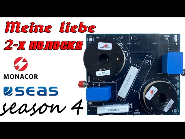
designs. Such things. I'll put this crossover together and get back to our discussion. Well, dear friends. Whether it's long or short, I'm a fellow crossover. I collected one copy in order to connect it to this column, this system and record test signals and make sure that the decision made was correct. Here you see what it looks like. It can be noted that Monacor did not even assume that the inductors were spaced along the axes, for example. That is, if one is horizontal, then it would be good
to place the second vertically in order to avoid the mutual influence of these coils. But it was done engineering correctly. The coils are located at such a distance that this mutual influence is of course not relevant, there is no point in discussing it, and unlike amateur designs, where fanatical perfectionists who do not have a base of real laboratories try to make oil better than the best...
The same Troels, for example, makes crossovers the size of a bast shoe, also in order to spread the components over a distance. I obviously won’t do this. Firstly, this is not even my work , as it were, but this is a factory sample, so all criticism is directed at the factory. OK? Yes, well, you see a resistor, a divider, input terminal capacitors, output terminals - for connecting speakers. Well, all that remains is to connect this crossover and run the test. Is he as good as I would like, as you and I would like. Well, then let's return to the discussion again. Well then. How long, how short... So I assembled the entire system itself, inserted this crossover, put it on top of this speaker, tweeter and connected both speakers...
naturally, the amplifier output, connected there. Everything is ready for testing and measurements. I'll take natural measurements first . Well, then we’ll think about how much we liked it all. Let's see. Here we see the resulting curve. What I can say right away is that the stitching in the region of 3-4 kHz is almost imperceptible. By the way, we can compare it with the estimated calculated one... This is what we got during our measurements. This is what we planned to get when we made estimates, you see... Even this failure, which is present in the frequency response of the tweeter, is not a bug of the system, it’s a bug of the tweeter, most likely it’s my measurement bug. Because you can’t measure it that way. Of course, I could take it to Klippel and measure it there, but this system is not capable of such a procedure. It cannot be called a complete,
established concept. We will talk about this later, we will return to this. However, you see, all these areas are repeated, the only thing here is that I got a slight rise, here a slight dip, but in general this is probably good... I see 200 Hz and where Baffle Step we should have compensated... Well, it looks like we compensated. Maybe we could lay it down a little more, but we'll see how it sounds. At the same time, I will make a measurement, as people asked me in the REW program, so that someone may find it more familiar, more interesting.. If I
can even fit the file to someone who needs it, that’s acceptable. We measure from 100 Hz Let it go up to 20,000, let’s check the level. Naturally, it’s small, but it’s enough for us.. Well, we got this curve, which, in principle, beats the same thing - this is a 7 kHz dip in the tweeter. This 3-4 stitching is quite correct, very similar to this measurement. We'll probably end here . Well, of course, Baffle could have been tweaked a little more. I may still do this. Let's see. This video is not intended to give you tools for repetition. Not at all. With this video I just wanted to show what depends on what when forming, when constructing an acoustic systems when developing an acoustic system. It is very important to convey at least my thoughts about the choice of configuration, the relationship of the speakers to the problem being solved. Or more precisely, how the task affects
the choice of speakers, the choice of configuration, the choice of partition strips, and so on. Generally speaking, this was the main task. And in the next video I will assemble a second such filter, connect both speakers, record a test video with sound on my old and new sets of tracks in order to give you at least a superficial impression of how it all sounds, and discuss other possible actions with these speakers. Once again, this is one of thousands of configuration options for these two, even just
these two speakers. That is, there may not be thousands of them, but a dozen combinations could be found. I showed you only one live, I showed two in the emulator over there in a program that beats quite well, as you can see with the results of live measurements. Well, it’s true that these measurements are curves. Once again, if I took this to either an anechoic chamber or a Klippel analyzer, I would get an absolutely accurate frequency response. But this design is not up to the task... So long, my friends. Auf Wiedersehen
2025-04-11