15KVA ALTERNATORVFRONTVELEVATION HALF IN SECTION DRAWING IN AUTOCAD ELECTRICAL 2023
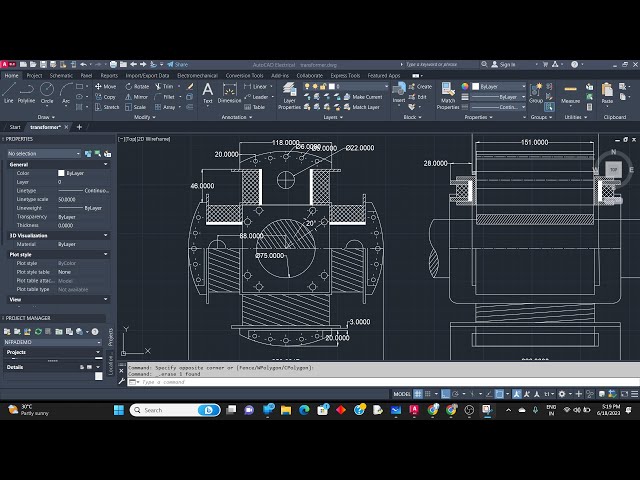
hello guys welcome to my channel uh in previous video we have on this 15 TV alternator drawing so next we have to draw this front elevation top half inch section so we'll see in detail uh the problem was given like this so first of all we have to draw Society is similar to this height so first thing we'll draw online and after that 162 152 and 150 these boxes will draw with a height of here it was given like 250 height okay so this is the height and 775 is a diameter 75 is the diameter 150 152 and 162. um two boxes we have to draw and one more this is coming out of this section portion that we'll draw 115 152 with the 250 height one more height so I'll move this part by picking the center point so Central Point is not enabled so this match snap is up because this part is completed next 75 is the height like diameter it is given for 75 is the height 280 random I'll take and the 75 is the height so this side to keep it in Center at the center so one referenced line will draw from the midpoint you know so on reference line I have drawn from this tangent and then move this point this point now we can delete this now it seems let's get the center so don't bother about this length of the sharp it is okay with that now next is 162 we have to draw the height height is not given so we have to take one random height 162 . foreign okay now this portion we have drawn so saying we have to take the top okay before that this section is also given this winding part that is like this is the taped portion so here you can see this step question is there okay this width is similar to this bit okay so we have to consider the width of this like a 206 . 206 was given and this section part is separately given here 46 . before this drawing this section will draw the end view of this coil so 46 is the width so apologies so this part is for on this one name okay this is different okay if any uh dimensions are not given then we can consider the dimensions for drawing purpose only not the actual design so from here here it is given 20 and after that on this port this part to this part 28 okay so we'll consider that this portion differently and from here to here 28. 28 this I'll consider in feet not it 28 5. so in between this it is not given so we'll consider this one only 46 okay from this line to in this line I'll draw on 26th line so Dimensions line and copy this so 28 we have drawn so one more 20 is there we will trim this portion 20 12.
we'll copy this part so here this height I have taken 25 and from this part if I this this section is 5 and this length I have taken from this end to this end so we'll print this point next part is hatching this is solid for this winding part is completed so next part is what we have to we won't return the shaft not sharp this whole you know this face okay so here this Dimension is not given but we can consider like from this part to this part you can consider this Dimension that is 62 okay foreign to 62 will take 62 . so here this point is not shown exactly but you can take one reference line in between 62 this is a reference line I'll draw next you can mirror this part foreign so simply we delete these hatchings on this part only we have to take online because it is given that 20 is the height so this frequently extend little bit now we have to trim all these points which is not needed thank you so make sure that you have to draw a line it's it is showing perpendicular see so this portion is extended this till point in this point so half of the section is hatching done like this we have to extend these are lines next hatch foreign so as we can see here these are the lines dotted lines shown here these are the codes these are the holes okay this is a pole which is shown from the side view okay now we have to place that this winding section on the hole okay so after this point again this 20 to 22 is the width and height we are going to consider this point only from this section too this section okay as we have already drawn this point we can take the dimension from this point to this point so 140 it is showing so 114 to 220 to 220. you have to draw one rectangle so 220 is the width and 120 is the height as we can see here from this point to this section 140. then take one midpoint will delete this reference line I'll move this by clicking from the center point so you can see here this portion is again here which is available and if we cross check this point it is placed in line it is placed in line so we'll take on reference line okay actually that was in assembly it was shown like this here it also take this section but in a assembly drawing it is like both side we are showing the coil so we'll mirror this okay you know I'll copy this before that we will trim this part everybody because directly when you pick all this point now this objects and place at the center as we can see here 152 is the touching point of this coils so simply you can pick these points and move it to pick this point so this completes okay you can delete this because it's not needed now simply will mirror this point but just pick them with a point it is difficult to find the midpoint while any rest option is available say this ends no just from this point onwards you have to take one line and draw one perpendicular line because it is a through hole which is seen from there from Quadrant I am taking if this now we can trim this line it did not need it because yes okay one more through hole is there this portion foreign so here we can see till this point that hatching is visible here this we have to extend till this point as we can see here and until this point click here you have to draw online yeah if here this hatching was in fence type so simply will select the searching and this line we'll measure it we're selecting the midpoint okay so this portion also completes and we'll draw online reference line okay the same reference line you have to take okay I'll take it little top five now we can delete this reference lines so this is a tape portion which is available here and this portion is also not complete with like here you can see so from this point so sometimes we may need a nearest Point at that time we can select from this point I'll take one line and perpendicular join it and take the trim command and remove this lines this line is also not needed in this line the red line is also not great now next hatching we have to take so by seeing the assembly diagram this portion is there from this point to this point will take let's check this point in the distance so 590 we'll round reference line midpoint foreign s are not needed now here you can see this this plan is there only for the top section and at the bottom it is not there so these lines will remove so let me check here this portion is ending up to this point so what we can do if we can reference line will take it we'll draw here this is ending up that and one more reference line will take and you draw here like this and this portion we have to take okay so from here I'll take one reference line so for anything that we can think that how we can draw and these portions we have to complete like this or else it is not possible if we are seeking for all the details and so small portion is shown here and some key that is 8 is height width and 162. we will consider foreign height height and length okay 12 by 162 we'll draw one line rectangle with 162. and 12.
okay this Sanctuary 2 place here no take the midpoint but again as we can see here this point is touching these lines are attaching to this point so these who is coming extra so we'll remove these points new thanks hatching I think it was eight but only single line is shown so we'll delete here we have to show one Center Line this should be Center Line foreign thank you let hatching in this neckline was passed so let me connecting once again so now if you see this much portion was trimmed okay so these all things are visible so here take to this point is completed okay now if we see this line is shown correctly and this point is also correct so only one this point is there hello so this point these lines we have to trim because it is not shown in the diagram not in the diagram because it is not necessary to show so at most this diagram completes and it should be 28 from this point to this point this line this line to this Edge it should be 28 so foreign this perpendicular and now if we check 152 162 . let me delete this topic is instead so all the dimensions we have to show so this ends the diagram so one more point is left here curving is given we can give the curving if it is necessary okay the radius have taken and given the radius of 10. and next we have to draw the shaft bendings same I take on the Curve mirror it so this portion were to keep disabled in the same point I'll copy here but here this portion I will rotate you know next hatching should be done which will be 220 . so this completes the drawing and hope this video is helpful for you and try to practice these things and don't forget to subscribe to my channel and like the video and share who all need this kind of information and keep watching for next video thank you
2023-06-24